
"Custom SMT Nozzle & Gripper Acceptance Testing: The SM-CNG Series Verification Workflow"
A four-gate acceptance workflow for verifying custom SMT nozzles and grippers on your own mounter, feeder setup and component before production release.
Aug 15, 2026 · Updated Aug 31, 2026 · Jason Wu
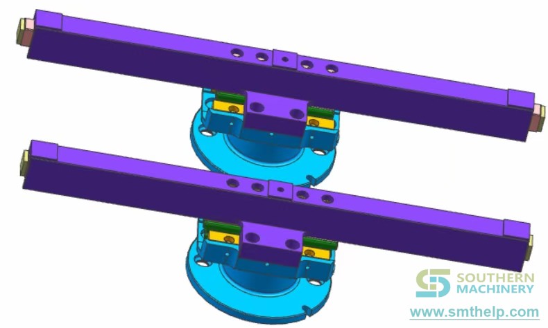
The custom tooling arrives, the drawing matches, the finish looks clean — and three hours into the first shift the connector still tilts on release. Custom nozzle and gripper projects do not end at the machining stage. They end when someone can prove, with recorded numbers from your own mounter, that the tool picks the real part, carries it through the real cycle, and releases it without a mark. Most tooling disputes are not design failures. They are acceptance failures.
The SM-CNG series covers customized nozzles, vacuum cups and mechanical grippers built for components that standard tooling handles poorly. What follows is the acceptance workflow we ask buyers to run before they release that tooling to production.
Why unverified custom tooling breaks quality, capacity or cost
Approving tooling on appearance alone pushes every problem into live production, where it costs most.
- Visual inspection cannot see vacuum behaviour. A cup that measures correctly may still leak against a textured, vented or domed surface, producing intermittent pickup that only appears at speed.
- Fitment errors mimic design errors. If the tool seats a fraction off in the head, or the offset was never re-calibrated, a sound nozzle generates X/Y and rotation defects blamed on the design.
- Release is harder than pickup. Sticking and spring-back cause shift and tombstoning after the head has left the position, so the operator sees a defect with no obvious cause.
- Manual workarounds hide the cost. Lines that skip verification end up hand-loading the difficult part "just for this batch", which quietly caps capacity and adds handling damage.
- No baseline means no recourse. Without acceptance criteria written before the trial, buyer and supplier argue about opinions instead of comparing data.
The Four-Gate Tooling Audit
Run these gates in order; each has a pass condition agreed before the tool ships and produces evidence you can send back if revision is needed.
1. Incoming dimensional gate. Before the tool goes near the mounter, compare it against the approved drawing: critical dimensions, contact-surface geometry, vacuum port diameter, jaw opening and machining finish. Check for transit damage and photograph anything questionable. Ten minutes here protects hours of line time.
2. Head fitment and offset gate. Mount the tool on the assigned placement head and confirm it locks positively, the machine recognises it during setup, and the vision system reads both tool and component. Re-run offset calibration before any board is placed. Tooling built for a specific head family fails loudly if this step is skipped.
3. Dry-cycle motion gate. With no paste and no board value at risk, cycle the tool through the full path: pick from the actual feeder or tray position, hold through travel and rotation, clear surrounding components, then release. Watch for interference, marking and delayed release. Mechanical problems belong here, not in a soldering post-mortem.
4. Live-batch data gate. Now run a controlled batch on real PCBs at production program and speed. A batch of 100–500 placements is a common starting point; the right number depends on component value, volume and risk. Record pickup stability, offset and rotation trend, marking and AOI findings, then approve, revise or reject against the agreed criteria.
The Vehicle: how the SM-CNG custom nozzle and gripper works
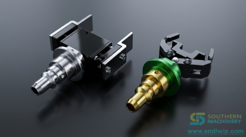
An SM-CNG tool starts from your component: datasheet or photographs, mounter and head model, feeder or tray presentation. The design then decides how the part is held — vacuum against a sealed flat face, a shaped cup straddling an uneven top surface, a multi-port cup for large shields, or mechanical jaws where no usable vacuum surface exists. Tall and heavy parts get extra attention on hold force and travel speed, because a tool that picks reliably at low speed can lose the part on a fast index. The mounting interface is machined to the head standard for native-like setup and calibration.
| Parameter | Specification |
| --- | --- |
| Tool types | Vacuum nozzle, shaped/multi-port cup, mechanical gripper, jumper-wire tooling |
| Component scope | Odd-form, fragile, tall, heavy, connectors, shields, non-flat top surfaces |
| Mounter compatibility | Panasonic, JUKI, Fuji, Yamaha, Samsung, ASM, Universal head standards |
| Design inputs required | Component datasheet / 3D model / photos, mounter and head model, feeder method |
| Body materials | Hardened tool steel, aluminium alloy, engineering plastics; ESD-safe options |
| Contact surfaces | Rubber, silicone or conductive elastomer pads for marking-sensitive parts |
| Vacuum configuration | Single or multi-port, sized to seal area and component mass |
| Acceptance evidence | Dimensional report, dry-cycle result, live-batch placement data |
| Typical trial batch | 100–500 placements, agreed per component value and risk |
Where it fits
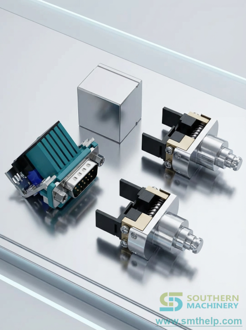
The tool is small; its influence runs the length of the line. Upstream, feeder or tray presentation decides whether the tool ever gets a clean shot at the part, so presentation and tooling are specified together. At the mounter, the accepted tool takes over a component previously hand-placed or fed at reduced speed. Downstream, post-reflow AOI becomes the audit trail: offset and rotation trends show whether the tool holds up across a shift, not just a demo. On mixed-technology products the logic extends to THT insertion, soldering and inspection stations.
The ROI case
Build the case from your own numbers. Capacity: a component that previously needed manual placement or a slowed index returns to full machine speed, visible in cycle time per board. Quality: stable pickup and clean release cut shift, tombstoning and marking, lowering rework hours and scrap on high-value assemblies. Labour: the operator nursing a difficult part moves to supervised work across several machines.
Multiply reject rate and rework minutes by monthly volume, add line-stoppage cost, and compare against tooling and validation cost. For high-mix work the payback is usually flexibility; for steady volume it is first-pass yield. The four gates keep the estimate honest — each produces a measurement that either confirms the assumption or sends the design back. That audit-and-improvement loop closes the gap between quote and reality. Treat any figure as a planning benchmark to test against your own data.
Your next step
Send the component datasheet or photographs, the mounter brand and head model, the current feeder or tray presentation, and a short description of the failure — poor pickup, sticking, shift, damage or unstable release. We will say whether a custom nozzle, a gripper, a feeder change or a broader line adjustment fits, and propose acceptance criteria before anything is machined. Ask for a part list review, a demonstration or a quotation at the same address.
FAQ
How do I know I need custom tooling rather than a standard nozzle?
Look at the defect history. If a standard nozzle produces unstable pickup, sticking, rotation, marking or poor release on one specific component, the tool is the constraint. If the problem follows the feeder or spans many parts, fix presentation or programming first.
Is a dry run enough for final approval?
No. A dry run isolates mechanical handling issues cheaply, but real PCBs, production speed and the actual machine program expose behaviour that dry motion cannot. A controlled live batch remains the deciding gate.
What should I send if the first trial fails?
Component photos and datasheet, mounter and head model, feeder setup, a short video of the pickup or release moment, defect images from AOI or microscope, and the exact condition where the failure appears.
Jason Wu
Founder & CEO, Southern Machinery (Shenzhen Southern Machinery Sales and Service Co., Ltd.)
Email: jasonwu@smthelp.com / info@smthelp.com
WhatsApp: +86 13602562576
Catalog & manuals: file.autoinsertion.com | Machine photos: ph.smthelp.com
LinkedIn: linkedin.com/in/smtsupplier | YouTube: youtube.com/c/Smthelping
Comments
Comments appear after approval.