
Your Placement Machine Is Fine. The Last Four Millimetres Are Not.
When a connector will not place reliably, the temptation is to blame the mounter. The failure is almost always the interface between part, feeder and pickup.
Jul 2, 2026 · Updated Aug 29, 2026 · Jason Wu
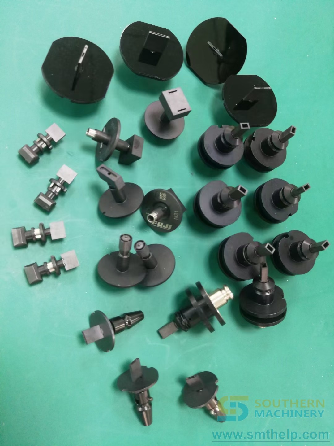
The mounter holds ±0.05 mm all day on 0402s. Then one connector shows up, and suddenly you have a manual placement station.
The machine did not get worse. What changed is the last four millimetres — the interface between the component, the feeder and the pickup tool. Standard nozzles are designed for a flat, predictable surface with a stable centre of gravity. A connector with a tall body, an uneven top face and pins that bend has none of those properties.
So the machine gets blamed, and a person gets hired to do the job by hand.
The seven symptoms of a nozzle problem
You are usually looking at a tooling problem, not a machine problem, when you see:
- Low pickup rate from the feeder or tray
- Component rotation during travel
- Misalignment at placement
- Scratched or damaged surfaces
- Parts dropped before placement
- Manual rework after automated placement
- Slow cycle time because operators compensate for unstable handling
In high-mix EMS work these symptoms are expensive in a quiet way. The part is technically placeable, but not stable enough for repeatable production — so it quietly consumes engineering time every time that board comes around.
The Failure-Mode Brief: what to assemble before you ask for tooling
Custom tooling projects fail from vague briefs, not from bad machining. Six inputs, and the order matters.
1. The component. Datasheet or drawing, plus a 3D model if one exists. Body geometry, weight, centre of gravity and what surfaces you are allowed to touch.
2. The failure, on video. Sixty seconds of the actual pickup failing tells an engineer more than a written description. Where does it slip, rotate or drop?
3. The machine. Brand and model. Nozzle shank, vacuum budget, Z-travel, placement force limits and what the existing nozzle library already holds.
4. The feeder. Tape, tube, tray, stick, bowl, belt or custom. The feeder determines the approach vector and how much tolerance the pickup has to absorb.
5. The target. Output per hour and the defect level you can actually live with. These two numbers decide how far the design has to go.
6. The constraint. ESD, cleanliness, no-mark surfaces, temperature, or a part you cannot grip on the top face at all.
Most requests that arrive as "we need a custom nozzle" turn out to need one of three different things: vacuum pickup with a shaped contact face, mechanical gripping for parts with no vacuum-friendly surface, or a material change — anti-scratch or anti-static — on a geometry that is already close. The brief is what tells you which.
How we build the tool
Consultation and needs analysis. We review the component, machine model, feeder method, production goal and failure mode. The useful output is a written statement of what has to stop happening.
Engineering and 3D design. Contact geometry, pickup force distribution, material selection and, where the part allows, vacuum versus mechanical grip. Anti-scratch and anti-static materials are specified here rather than discovered later.
Precision manufacturing. Built for your machine platform — the shank, seal and vacuum path are machine-specific, so this is never a generic part.
Quality checking and delivery. Verified against the failure mode you described, not against a drawing tolerance alone. The test is: does it do the job on your machine, with your feeder, at your target rate?
Where it sits in the line
On the SMT side, custom nozzles and grippers extend an existing mounter's range — you are not buying a machine, you are removing the one part number that forces a manual station.
On the THT and odd-form side, they pair with insertion machines and robotic cells: the gripper is what lets a robot handle a relay, transformer or terminal that no tape feeder will ever present cleanly.
In board handling and inspection, they matter more than expected. Delicate finishes and tight keep-out zones mean the pickup tool is often the difference between a part that survives handling and one that arrives damaged at AOI.
For traceability, a stable pickup is a prerequisite. You cannot get meaningful placement data from a process that needs manual correction to hit yield.
Close the loop
Keep a tooling register. Every time a part number forces manual placement, log the part, the machine, the feeder and the failure mode. Review it quarterly. Three entries against the same connector family is a tooling project with a business case attached — and you will have the brief already written.
Your next step
Send the component datasheet or drawing, the SMT machine brand and model, the feeder type, and a short video of the current failure. We will tell you whether you need vacuum, mechanical grip or a material change — and if your existing nozzle library can be modified instead, we will say so.
Catalog and documentation: file.autoinsertion.com. Tooling and machine photos: ph.smthelp.com. Videos: youtube.com/c/Smthelping.
Jason Wu
Founder & CEO, Southern Machinery (Shenzhen Southern Machinery Sales and Service Co., Ltd.)
Email: jasonwu@smthelp.com / info@smthelp.com
WhatsApp: +86 13602562576
Catalog & manuals: file.autoinsertion.com | Machine photos: ph.smthelp.com
LinkedIn: linkedin.com/in/smtsupplier | YouTube: youtube.com/c/Smthelping
Comments
Comments appear after approval.