
How to Build a Lights-Out THT Line: Southern Machinery's Automated Through-Hole Assembly Blueprint
Lights-out THT is not about emptying the floor overnight. It is about counting every place a person touches a board, then retiring those touches one station at a time.
Aug 4, 2026 · Updated Sep 1, 2026 · Jason Wu
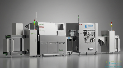
How to Build a Lights-Out THT Line: Southern Machinery's Automated Through-Hole Assembly Blueprint
On most EMS floors, the through-hole section is the last place where people still stand in a row. Operators hand-insert capacitors, relays, transformers, and terminals, then carry racks of boards to the wave solderer. Every touch is a chance for a missed, floating, or reversed part, and every touch is a shift limit you cannot schedule around. A lights-out THT line does not remove your operators. It removes the touches between the machines.
The cost you haven't named: the touches between machines
Cost studies price the insertion work itself. The money leaks in the handling around it.
- Manual insertion defects. Hand placement produces four recurring fault classes: floating components, missed insertions, misinsertion, and reverse-polarity insertion. Automatic insertion with 360-degree orientation control eliminates all four at the source.
- Training cost you pay twice. DIP lines staffed by young, mobile operators carry high training cost and unpredictable output.
- A ceiling set by shift hours. Manual output scales with headcount and shift length; an automatic inserter runs at rated CPH continuously.
- Boards waiting between stations. Where people carry boards, work-in-process piles up at the bench and again at the wave solderer.
- Data that stops at the bench. A hand-inserted board leaves no program and no feeder record, so an AOI finding cannot be traced to a cause.
The Handoff-Count Framework
A lights-out THT line is configured, not bought. Count every place a person touches a board, then retire the touches in this order.
1. Count every handoff. Walk one board from bare PCB to soldered PCBA and log every touch: destacking, manual insertion, rack loading, wave solder input, lead cutting, unloading. Each entry is a candidate for automation, not a given. Through-hole usually carries several times more touches per board than SMT.
2. Sort the mix, then assign one machine per class. Split the BOM into radial, axial, odd-form, and pin/eyelet/terminal. Radial covers electrolytic, ceramic, box, and film capacitors, transistors, diodes, LEDs, tact switches, and fuses. Axial covers parts with a lead at each end. Odd-form covers relays, transformers, and connectors that will not feed from tape. Terminals need their own head. Anything left without a home keeps an operator at the bench.
3. Link the stations with board handling. Loaders, unloaders, conveyors, and turn conveyors make reduced-operator running practical, because nobody carries boards. Without them, each insertion machine stays an island with a queue that needs a person.
4. Instrument the touches that remain. Reel and bowl replenishment, program changeover, dross control, and first-article inspection still need judgment. Give each a count and a reason, then review the list quarterly.
The vehicle: Southern Machinery's THT insertion and soldering family
Four machine families plus the handling between them carry the framework. Southern Machinery has built this equipment in Shenzhen since 2011.
- Count handoffs to board handling. Loaders, unloaders, conveyors, and turn conveyors move boards between insertion, wave soldering, and lead cutting, and cover NG/OK separation and buffering.
- Radial class to the S-3000 series. 18,000 CPH spec speed, 360-degree insertion in 1-degree increments, inward or outward clinching, and offline, Excel, USB, or visual-teach programming.
- Axial class to the S-4000 series. The counterpart for lead-at-each-end parts, specified alongside the radial machine.
- Odd-form class to the S-70LD and S-7000/S-7900 series. Built for relays, transformers, and electrolytic capacitors with unusual lead configurations—the parts that never fit radial or axial tape.
- Pin, eyelet, and terminal class to the S-7020 series. Inserts from bulk or reel packaging with 360-degree orientation and inward or outward clinching, on boards up to 380 x 280 mm.
- Solder in one pass to the S-WS350B lead-free dual wave. Three PID preheating zones, +/-1 to 2 degrees C accuracy, 50 to 350 mm PCB width, 300 to 1800 mm/min conveyor speed.
Specification note: the figures below are catalog values. Real throughput depends on your component mix, feeder count, changeover frequency, and board design, so board size, conveyor speed, power, and feeder configuration should be confirmed at quotation.
Watch the walkthrough: https://www.youtube.com/watch?v=omxIkpIkxS4
Specifications
| Parameter | Value |
|---|---|
| Radial insertion speed | 18,000 CPH spec speed, S-3000 |
| Terminal insertion speed | 12,000 CPH, S-7020 series |
| Max PCB size | 380 x 280 mm, larger customizable |
| Insertion angle | 360 degrees in 1 degree steps |
| Clinching | Inward or outward |
| Hole clearance | About 0.5 mm over lead size |
| Terminal packaging | Bulk or reel |
| Wave PCB width | 50 to 350 mm, S-WS350B |
| Wave conveyor speed | 300 to 1800 mm/min |
| Preheating zones | 3 PID zones |
| Wave temperature accuracy | +/-1 to 2 degrees C |
| Power, terminal machine | Single phase 220 V, 2 KVA |
| Power, wave soldering | Three phase 380 V, 415 V compatible |
| Programming | Offline, Excel, USB, visual teaching |
The loop: let insertion data re-plan the line
A configured line keeps producing the evidence you need to re-plan it. Each run returns cycle counts, feeder reload intervals, changeover times, and AOI defect classes by part. Feed that back quarterly: high-defect parts move to a dedicated head, feeders that starve the inserter get a second pack, slow programs get offline templates. That loop separates a line automated once from a line that keeps giving operators less to do. Push the same data into MES, and a field return traces to a program revision rather than a guess.
Your next step
Send your BOM split by part class, board size range, monthly volume, and changeover frequency. Southern Machinery will map them against the insertion families above, propose a handling layout, and name the stations that still need a person. Reach Jason at jasonwu@smthelp.com.
FAQ
Does lights-out mean nobody on the floor?
No. It means fewer operator touches per board, not zero. Insertion, board transfer, and wave soldering run automatically, while reel replenishment, changeover, dross control, and first-article inspection still need a person. Most lines settle at one or two operators per shift.
Which parts have to stay manual?
Whatever your machine set cannot feed, which is why the sort in step two matters. Wire harnesses, large mechanical assemblies, and boards laid out without auto-insertion rules land there.
Do my PCB designs need to change?
Often yes. An insertion hole about 0.5 mm larger than the lead, consistent lead spacing, and keep-out areas around tall parts are what let a machine place reliably. Review layouts against auto-insertion rules before tooling.
How fast does the investment pay back?
Published THT case material references ROI windows as short as one year for wave-soldered through-hole assembly. Your payback depends on labor cost, shift pattern, and volume, so model it on insertion stations replaced per shift.
Can I build the line in stages?
Yes, and most buyers do. Start with the highest-volume part class, usually radial, add board handling between machines you already own, then add odd-form and terminal insertion as volumes justify.
---
Jason Wu
Southern Machinery — SMT/THT Assembly Automation
jasonwu@smthelp.com
youtube.com/c/Smthelping
Comments
Comments appear after approval.