
PCB Inspection Methods and Common Defects: SPI, AOI and X-Ray with the SH8650
Every PCB line produces defects; what separates a profitable line from a struggling one is how early each defect type is caught.
Aug 16, 2026 · Updated Aug 31, 2026 · Jason Wu
A paste bridge costs a few seconds to fix at the printer. The same bridge found at functional test costs a rework cycle, a thermal excursion and a traceability record. Found by your customer, it costs the account. Nothing about the defect changed — only where it was caught. Every assembly line makes defects; the ones that stay profitable are the ones that catch each defect type at the cheapest available station, and that is a design decision, not a matter of diligence.
Why late defect detection breaks quality, capacity or cost
Manual visual inspection is the default fallback, and it fails in predictable ways.
- Human judgement is not repeatable. Two inspectors grade the same fillet differently, and one inspector grades it differently at hour seven than at hour one. There is no baseline to trend against.
- Some joints cannot be seen at all. BGA, QFN, shielded modules, connectors and press-fit terminals hide their joints under the body. No lamp and no magnifier reaches them.
- Paste is measured after the fact, if at all. Print defects create most downstream solder defects, yet paste height, area and volume usually go unmeasured until components are already placed on top of them.
- Manual inspection becomes the bottleneck. A dense THT board has hundreds of joints. Inspecting them by eye at line rate is not realistic, so sampling replaces inspection and escapes rise.
- No data means no root-cause work. Without per-pad and per-component results, engineers rework symptoms instead of fixing the feeder, nozzle or stencil that is actually drifting.
The Defect Escape Map
Build this before you buy anything. It is a table of your own defects, not a catalogue comparison.
1. List your defect families. Paste bridges and insufficient paste, tombstoning, missing or misaligned parts, wrong polarity, solder bridges, cold joints, insufficient wetting, lifted pads, BGA voids, and for THT, incomplete insertion or poor clinching. Use your own failure records, not a generic list.
2. Mark the earliest station that can see each one. Paste defects belong to SPI, immediately after printing. Presence, polarity, position and orientation belong to pre-reflow AOI. Fillet quality belongs to post-reflow or post-wave AOI. Hidden joints belong to X-ray. Anything unmatched is a gap in your line.
3. Cost each escape path. For every family, record what it costs when caught at that earliest station, at functional test, and at the customer. The ratio between those three numbers tells you which station to fund first, and it is rarely the one people expect.
4. Test the changeover and false-call load. For your highest-mix product, ask how a new program is created, whether offline programming is supported, and what false-call rate the program settles at. An inspection station that stops the line with false calls has moved the bottleneck rather than removed it.
The Vehicle: how the SH8650, S-AO600C and X-ray stack work
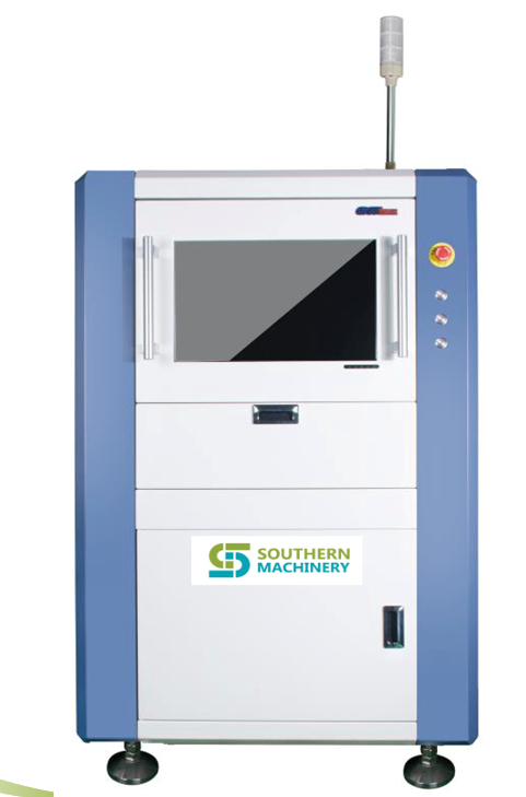
Inspection is a set of stations, not one machine. The SH8650 3D SPI measures the paste deposit on every pad straight off the printer, comparing height, area and volume against the program so a bad print is caught and cleaned before a single component is placed. Inline AOI — for example the S-AO600C — runs cameras over the board pre-reflow for presence, polarity, position and orientation, and again post-reflow or post-wave for joint quality and insertion completeness. X-ray inspection looks through the package for the joints optics cannot reach, with geometric magnification up to 120× and system magnification up to 1000×. SMD component counters and X-ray chip counters verify reel quantities at goods-in and kitting, so a run never starts short.
| Parameter | Specification |
|---|---|
| SPI model | SH8650 3D solder paste inspection |
| SH8650 max PCB size | 510 × 460 mm |
| SPI measurement | 3D paste height, area and volume, per pad |
| AOI model | S-AO600C inline AOI (pre-reflow, post-reflow, post-wave) |
| X-ray power supply | Single-phase AC 110–220 V, 50–60 Hz |
| X-ray geometric magnification | Up to 120× |
| X-ray system magnification | Up to 1000× |
| Material control | SMD reel counters and X-ray chip counters at goods-in and kitting |
| Configuration | Inline conveyor-matched, or offline for QC and rework cells |
| Programming | Program per board with offline creation for fast changeover |
| Data output | Results linkable to MES for traceability and SPC |
Confirm the board size envelope against your largest and smallest panels, and confirm package types against your BGA and QFN population, before selecting between 2D and 3D measurement.
Where it fits
Inspection stations are placed where the defect is created, not where it is convenient. Printing → SH8650 SPI. Placement → pre-reflow AOI. Reflow → post-reflow AOI. THT insertion and wave soldering → post-wave inline AOI to verify insertion depth and fillet formation. BGA and bottom-terminated packages → X-ray, inline or in a QC cell. Goods-in and kitting → component counting. Because Southern Machinery builds the whole line — printers, placement, insertion, reflow, wave soldering, board handling and inspection — conveyor height, width, handshake and workflow are matched across stations, and one support team covers the line rather than three vendors negotiating an interface.
The ROI case
Model three effects rather than one. Containment: a defect caught at its earliest station costs a fraction of the same defect caught downstream, so the return scales with your escape volume and your rework rate, not with the machine's specification sheet. Labour and consistency: automated inspection replaces slow, subjective manual checking — particularly on THT boards with hundreds of joints — and applies identical criteria on every board and every shift. Process data: per-pad and per-component results reveal which feeder, nozzle or stencil aperture is drifting, which lets engineers fix causes instead of reworking symptoms, lifting first-pass yield over time.
Re-run the Defect Escape Map each quarter and after every new product introduction. That audit-and-improvement loop closes the gap between your planned yield and your actual yield, because defect families shift as products change. Treat any payback calculation as a planning benchmark built from your own escape and rework data.
Your next step
Send your board sizes, package list, current defect Pareto and line takt time. Our engineers recommend which inspection stations to add first, in what order, and whether inline or offline suits your mix — then quote the configuration. Email jasonwu@smthelp.com or info@smthelp.com, or WhatsApp +86 13602562576. Demonstrations on your own boards can be arranged.
FAQ
What is the difference between SPI and AOI? SPI measures the paste deposit immediately after printing, before placement, so it prevents defects from being built in. AOI inspects assembled boards — presence, position, polarity and joint quality — before or after soldering, so it catches defects already created.
When is X-ray necessary? When joints are hidden under the component body: BGA, QFN, shielded modules, connectors and press-fit terminals. Optics cannot see these, so X-ray is standard practice for automotive, medical and other high-reliability assemblies.
Can inspection be added to an existing line? Yes. Inline units are built to match standard conveyor height and width, and offline units serve QC and rework cells. Confirm board size, line speed and program workflow with the supplier for a clean integration.
Which defects does post-wave AOI catch that pre-reflow AOI cannot? Insertion depth and clinching on through-hole parts, plus fillet formation and bridging created by the wave itself — none of which exist yet at the pre-reflow stage.
Jason Wu
Founder & CEO, Southern Machinery (Shenzhen Southern Machinery Sales and Service Co., Ltd.)
Email: jasonwu@smthelp.com / info@smthelp.com
WhatsApp: +86 13602562576
Catalog & manuals: file.autoinsertion.com | Machine photos: ph.smthelp.com
LinkedIn: linkedin.com/in/smtsupplier | YouTube: youtube.com/c/Smthelping
Comments
Comments appear after approval.