
Solder Robot S-A300 / S-B400: Desktop Soldering Automation for THT PCB Assembly
Two desktop solder robots that turn hand-iron work into programmed, documented THT soldering with teach-pendant setup and ±0.02 mm repeatability.
Aug 9, 2026 · Updated Aug 31, 2026 · Jason Wu
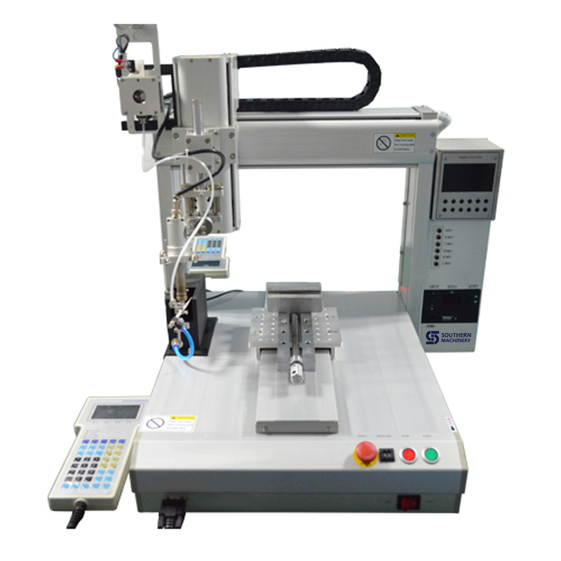
Solder Robot S-A300 / S-B400: Desktop Soldering Automation for THT PCB Assembly
Walk your rework bench at the end of a night shift and count the joints being touched a second time. In most THT shops the wave isn't the problem — the hand-iron positions are. Tip temperature drifts, dwell time varies between operators, and by hour six the fillet quality is a different process than it was at hour one. The S-A300 and S-B400 desktop solder robots exist to take that variance out of the joints reflow and wave can never reach.
The cost you haven't named: hand-iron variance
Most factories budget carefully for the printer, the mounter, and the reflow oven, then treat soldering iron work as a labor line item instead of a process.
- No profile, no record. A wave machine has a logged thermal profile. A hand iron has an operator, a habit, and a tip that was last dressed at an unknown time.
- Fatigue is a defect source. Cold joints, bridging, and disturbed solder cluster in the back half of a shift, when hand steadiness and dwell discipline both fade.
- Touch-up hides behind yield numbers. Post-wave rework is often counted as "normal work" rather than as scrap risk, so nobody costs the hours it consumes.
- Nothing transfers between runs. When the same board comes back next quarter, the soldering method lives in an operator's memory, not in a program file.
The Four-Point Hand-Solder Conversion Audit
Before quoting any soldering automation, treat the decision as a repeatable audit of your existing bench. Call it the Four-Point Hand-Solder Conversion Audit.
1. Inventory the joints, not the boards. List every position currently soldered by hand — connector terminals, transformer leads, fuse clips, LED pins, post-wave touch-up points — and record how many of each per board. Joint count, not board count, drives cycle time and payback.
2. Classify the approach angle. Sort those joints into perpendicular joints the iron can reach straight down, and angled or standing-lead joints that need the iron rotated. This single split decides whether you specify a three-axis or a four-axis machine.
3. Measure the variance you already pay for. Pull three months of AOI and ICT data and separate defects at hand-soldered positions from everything else. That delta is the number the robot is being bought to reduce, and it is your acceptance metric.
4. Define the changeover budget. Decide how many minutes a program change may take on your highest-mix product family. If operators must create and edit programs themselves, teaching-pendant programming is a requirement, not a preference.
The vehicle: S-A300 and S-B400 desktop solder robots
The audit maps directly onto how these two machines get deployed.
- Inventory the joints → programmed multi-point soldering. The robot carries a temperature-controlled iron on a desktop motion platform and feeds solder wire automatically to each recorded coordinate, covering spot joints, multi-point sequences, and in-plane patterns with the same dwell time on every joint.
- Classify the approach angle → three-axis or four-axis. The S-A300 is a three-axis machine (X, Y, Z) for flat multi-point work. The S-B400 adds an R axis with ±360° rotation for angled iron approaches and leads standing off the board plane.
- Measure the variance → ±0.02 mm repeatability. Both models specify ±0.02 mm repeatability on X, Y, and Z. Joint-to-joint consistency is what converts an unstable manual position into a stable, documented one.
- Define the changeover budget → teaching-pendant programming. An operator jogs the iron to each joint, records the point, and the robot replays the path. No offline CAM step is needed for most jobs, and programs are stored per product for the next run.
Specification note: exact cycle time, joints per hour, tip and wire specification, and fixture design are confirmed at quotation, because they depend on your board mix, pad sizes, and line layout rather than a single factory-wide default.
Specifications
| Parameter | Value |
|---|---|
| Model range | S-A300 (3-axis, XYZ) / S-B400 (4-axis, XYZR) |
| Working range | 300 × 300 × 100 mm (X × Y × Z) |
| R-axis rotation | ±360° (S-B400) |
| Repeatability | ±0.02 mm on X / Y / Z |
| Programming | Teaching pendant, program stored per product |
| Solder feed | Automatic wire feeder, feed rate adjustable per step |
| Power supply | AC 220 V, 50/60 Hz |
| Air supply | Dry air, 4–5 kgf/cm² |
| Machine footprint | 650 × 600 × 720 mm |
| Typical placement | Post-wave touch-up, THT cell, offline rework bench |
Because it runs on single-phase AC 220 V and needs only dry air, the robot drops onto an existing bench or a conveyor-adjacent position without facility changes. Fixtures are simple PCB holding jigs — often the same ones your operators already use.
Where it earns its position: power supply and charger boards, connector and fuse terminal blocks, LED lighting and display boards, automotive audio and vehicle power boards, LCD assemblies, and mixed SMT/THT medical and industrial control boards where reliability must be documented rather than assumed.
The loop: re-score the bench every month
Automation drifts the moment nobody looks at it. Build a loop around the machine: every month, re-run step three of the audit and compare hand-soldered defect rates before and after conversion, joint family by joint family. Review tip wear and consumable replacement intervals with your line lead, then move the next-worst manual joint family onto the robot. When a new product family arrives, re-classify its approach angles before ramping it. The loop is what turns one desktop machine into a standing process-control habit instead of a bench ornament.
Your next step
Send us your board size, the joint list you want converted, and your monthly output. We will return a configuration note covering whether the S-A300 or S-B400 fits, what tip and wire specification to plan for, the fixture approach, and which figures to confirm at quotation. Reach Jason at jasonwu@smthelp.com or on WhatsApp +86 13602562576.
FAQ
What is a solder robot used for?
It automates soldering iron work — spot joints, multi-point sequences, and in-plane patterns on THT assemblies — by moving a temperature-controlled iron and wire feeder along programmed paths at consistent temperature and dwell time.
What is the difference between the S-A300 and the S-B400?
The S-A300 is three-axis (X, Y, Z). The S-B400 adds a fourth R axis with ±360° rotation for angled approaches and joints not perpendicular to the board. Both share 300 mm X/Y travel, 100 mm Z travel, and ±0.02 mm repeatability.
Can it replace manual soldering in a small EMS factory?
For repetitive THT joints, touch-up, and post-wave rework it removes the hand-iron variance and frees operators for higher-value work. It is a lower-capital route than a full selective soldering line for high-mix, low-volume production.
How is it programmed?
Through a teaching pendant. The operator jogs the iron to each position, records the point, and the robot replays the sequence. Programs are saved per product so the same board solders the same way on the next run.
What does it need from the facility?
AC 220 V single-phase power and dry air at 4–5 kgf/cm², plus bench space for a 650 × 600 × 720 mm machine. Fume extraction and fixture details are confirmed at quotation.
Jason Wu
Founder & CEO, Southern Machinery (Shenzhen Southern Machinery Sales and Service Co., Ltd.)
Email: jasonwu@smthelp.com / info@smthelp.com
WhatsApp: +86 13602562576
Catalog & manuals: file.autoinsertion.com | Machine photos: ph.smthelp.com
LinkedIn: linkedin.com/in/smtsupplier | YouTube: youtube.com/c/Smthelping
Comments
Comments appear after approval.