
S580 Series PCB Strain Gauge Measurement for Reliable SMT Assembly
The S580 series strain gauge and SDL device map board flex in real time, so you catch strain that cracks BGA joints before it becomes a field failure.
Aug 7, 2026 · Updated Aug 31, 2026 · Jason Wu
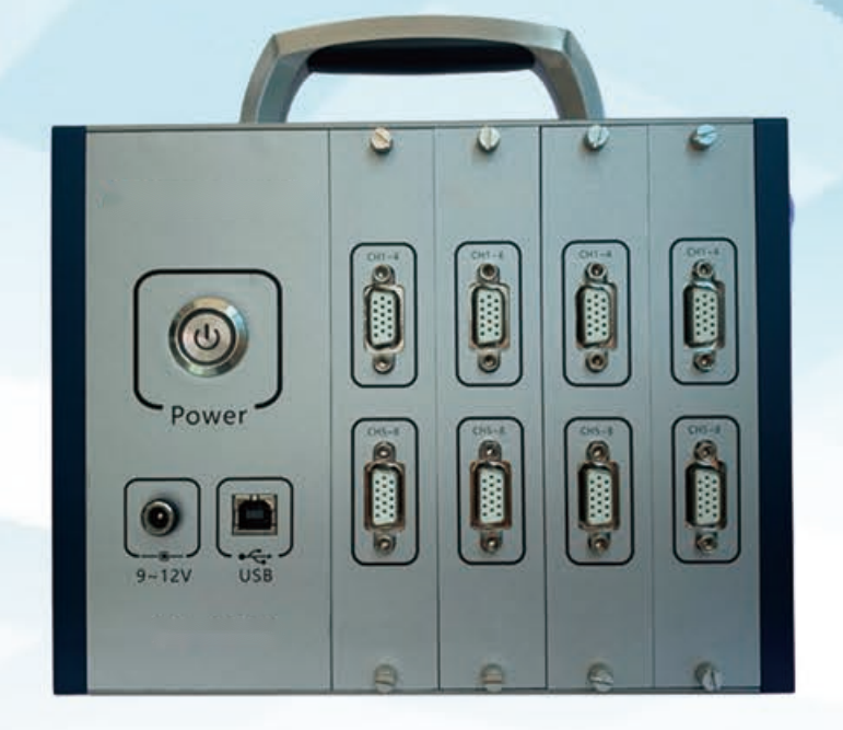
S580 Series PCB Strain Gauge Measurement for Reliable SMT Assembly
BGA and chip solder joints rarely crack at reflow — they crack later, when a board is flexed during depaneling, wave-solder pallet clamping, connector insertion or handling. By the time the return arrives, the production lot is gone and the cause is a guess. Strain you cannot measure is strain you will keep reproducing on the next build.
The cost you haven't named: invisible mechanical strain
Board flex is the failure mode most lines never instrument, which is why it survives into the field.
- Depaneling flex. Router, V-score or punch separation bends the board at the exact point where a BGA corner sits, seeding a crack that passes final test.
- Wave-solder clamping. Pallet clamps and board supports concentrate load on a few points; excess force transfers straight into solder joints.
- Insertion and test press-fit. Connector insertion and ICT/FCT fixtures push on the board, and without a measured limit, that push becomes a fracture.
- Field returns with no root cause. A cracked joint opens under thermal cycling at the customer site, and the line has no data to show which step caused it.
The Four-Step Strain-Limit Qualification
Turn board flex from a guess into a measured limit. Frame it as the Four-Step Strain-Limit Qualification.
1. Instrument the sample board. Embed miniaturized strain gauges with Wheatstone-bridge circuits into sample PCBs so the board reports its own bending, torsion and tension during the real process.
2. Walk the real process. Run the instrumented board through actual assembly — clamping, conveying, cutting, insertion, test — and collect strain data wirelessly at each mechanical step, not in a separate rig.
3. Map against the limit. Compare the measured strain map to the IPC/JEDEC-9704 strain limits and flag the step that exceeds the safe window, so the culprit is named instead of assumed.
4. Lock the validated fixture. Update the fixture, support tooling or process parameter that broke the limit, and freeze the corrected setup as the standard for that product family.
The vehicle: S580 series strain gauge with SDL measurement device
The framework maps onto how the S580 strain gauge and SDL series device work as a quality-engineering tool beside production.
- Instrument the sample board → printed gauges. The SDL series uses gauges printed directly onto the PCB, so no external sensor rig occupies line space and the board's function is unaffected; it converts mechanical deformation into a resistance change.
- Walk the real process → wireless capture. Strain data transmits wirelessly to a connected device at each mechanical step, giving real-time strain mapping across prototyping, qualification and field use.
- Map against the limit → standard compliance. The software maps results to IPC/JEDEC-9704 strain limits and reporting, so a process engineer can identify which step exceeds acceptable load before failures appear.
- Lock the validated fixture → reusable evidence. The validated process becomes the standard for the family, and the strain report supports customer quality audits and automotive or medical PPAP-style submissions.
Specification note: gauge type and mounting, measurement range, sampling rate, analysis software, minimum sensor footprint and process-step coverage should be confirmed at quotation, because they depend on your board material, layout density and assembly steps.
Specifications
| Parameter | Value |
|-----------|-------|
| Device | S580 series strain gauge + SDL series measurement device |
| Sensing | Printed / embedded Wheatstone-bridge strain gauges |
| Measures | Board bending, torsion, tension (real-time) |
| Transmission | Wireless to connected analysis device |
| Standard | Maps to IPC/JEDEC-9704 strain limits |
| Board fit | Space-constrained, thin / large-format PCBs |
| Process coverage | Depaneling, wave solder, insertion, ICT/FCT test |
| Lifecycle | Prototyping, qualification, field monitoring |
| Reporting | Strain maps and limit-compliance export (confirm) |
The loop: re-qualify on every new board family
Strain limits are per board, not per line. Build a loop: every time a new PCBA enters the line, instrument a sample, walk it through the real process, and compare the strain map to the accepted IPC/JEDEC-9704 window before high-volume ramp. Review historical strain reports with your reliability lead each quarter, and re-qualify any fixture that was modified since the last build. Treat qualification as a living record — the loop is what stops a board-flex crack from becoming a warranty claim you cannot explain.
Your next step
Send us your board size, assembly process steps and reliability requirements. We will return a measurement workflow outlining how the S580 series and SDL device integrate with your line, what gauge coverage to specify, and what to confirm at quotation. Reach Jason at jasonwu@smthelp.com or on WhatsApp +86 13602562576.
FAQ
What does a PCB strain gauge measure?
It measures mechanical deformation of the board — bending, torsion and tension — by converting strain into a change in electrical resistance, giving real-time quantitative stress data instead of a visual guess.
Why is strain testing needed in SMT assembly?
Board flex during depaneling, soldering, insertion and handling can crack BGA and chip solder joints. Strain testing per guidelines like IPC/JEDEC-9704 identifies which process step exceeds safe limits before field failures appear.
Does it work with existing SMT lines?
Yes. The sensors are embedded in sample PCBs, which then run through your normal assembly line; no line reconfiguration is required and data is collected wirelessly during the process.
Can it be used on production boards, not just prototypes?
The SDL series supports prototyping, qualification testing and field-use monitoring, giving visibility across the whole product lifecycle rather than only at design.
Which industries benefit most?
Automotive electronics, aerospace, industrial control, EMS and consumer electronics — anywhere board flex threatens solder-joint reliability and a field return is expensive to explain.
Jason Wu
Founder & CEO, Southern Machinery (Shenzhen Southern Machinery Sales and Service Co., Ltd.)
Email: jasonwu@smthelp.com / info@smthelp.com
WhatsApp: +86 13602562576
Catalog & manuals: file.autoinsertion.com | Machine photos: ph.smthelp.com
LinkedIn: linkedin.com/in/smtsupplier | YouTube: youtube.com/c/Smthelping
Comments
Comments appear after approval.