
SRT7001 Reel Terminal Feeder: Bridging SMT and Robotic Cells
A reel-terminal feeder that presents continuous-strip terminals for automated pickup on SMT and robotic lines, removing manual presentation at the pick point.
Aug 3, 2026 · Updated Aug 31, 2026 · Jason Wu
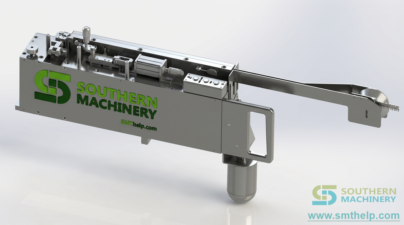
SRT7001 Reel Terminal Feeder: Bridging SMT and Robotic Cells
The pick point on a mixed SMT/THT line is where reel-fed terminals stall automation. Your mounter is tuned for repeatable nozzle pickup, but a continuous-strip terminal has no natural home on the reel — so an operator steps in, hand-places it at the nozzle, and the cycle waits. That manual touch adds variance, fatigue, and a stop every time the terminal family changes. The SRT7001 Reel Terminal Feeder removes that touch by presenting each terminal at a fixed pickup location for your mounter or robot.
The Cost You Haven't Named
Most factories design their SMT line around the mounter and treat terminal presentation as an afterthought — a problem somebody solves by hand at the pick point.
- Manual presentation at the nozzle. An operator positions each reel terminal by hand before the robot or mounter picks it, adding a stop and a person to every cycle.
- Variant-driven downtime. When the BOM changes the terminal family, pitch, or pilot-hole pattern, the hand method has to be re-learned, and first-piece yield drops until the cell settles.
- Mechanical instability at pickup. A feeder built only on friction lets the strip drift laterally, so the nozzle or gripper arrives at a moving target and misses or damages the terminal.
- No clean handshaking. Without a defined ready-to-pick, advance, fault, and safe-stop signal set, the cell cannot coordinate the feeder with the rest of the line.
The Cell-Integration Readiness Audit
Before buying a reel-terminal feeder, frame the decision as a repeatable audit rather than a one-off part. Call it the Cell-Integration Readiness Audit.
1. Confirm the terminal package. Review strip pitch, pilot-hole layout, terminal shape, reel condition, and any cover-tape or interleaf material so the feeder and part are matched before any trial.
2. Define the pickup interface. Match the feeder's presentation location to the nozzle, gripper, or end-effector and verify clearance through the full pickup motion on a real board.
3. Map the controls handshake. Document ready-to-pick, advance, fault, reset, and safe-stop behavior between feeder and mounter or robot, including 24 V I/O for robotic cells.
4. Set the accepted handoff target. State what a good run looks like: repeatable pickup location, zero manual touch at the point, and every fault recoverable without stopping the line. That becomes your acceptance test.
The Vehicle: SRT7001 Reel Terminal Feeder
The framework above maps directly onto how the SRT7001 is deployed in a real cell.
- Confirm the terminal package → positive pilot-hole indexing. The feeder engages the terminal strip's pilot holes rather than relying on friction, so each index advances a known, repeatable distance regardless of tape condition.
- Define the pickup interface → adjustable guide rails and presentation zone. Adjustable rails constrain lateral movement, and the presentation area gives SMT nozzles or robotic grippers a fixed location to pick from, validated once per setup.
- Map the controls handshake → separate indexing and tape drives with 24 V I/O. Separate drives handle terminal indexing and cover-tape or interleaf handling, and 24 V I/O handshaking gives a robotic cell a clean ready-to-pick, advance, fault, and safe-stop sequence.
- Set the accepted handoff target → stable electromechanical interface. By presenting continuous-strip terminals consistently, it removes manual presentation at the pick point and makes downstream placement or insertion easier to commission and maintain.
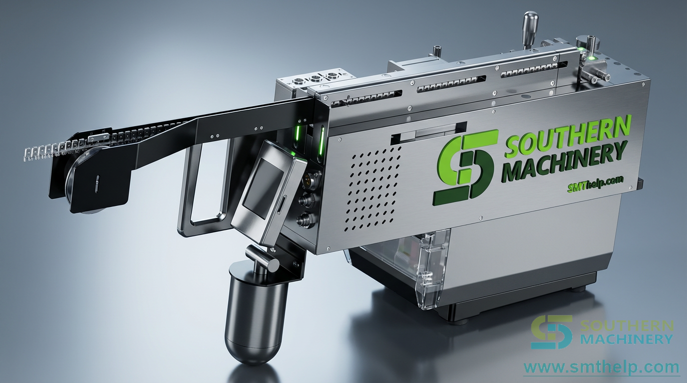
Specification note: pilot-hole pattern, strip pitch, terminal geometry, drive spec, I/O protocol, and feeder positions should be confirmed at quotation, because they depend on your actual terminal strip, target platform, and line layout rather than a single default.
Specifications
| Parameter | Value |
| Terminal type | Reel-fed continuous-strip terminals |
| Indexing method | Positive pilot-hole engagement |
| Lateral control | Adjustable guide rails |
| Presentation | Fixed component presentation zone for nozzle / gripper |
| Drives | Separate terminal-indexing and cover-tape / interleaf drives |
| Control interface | 24 V I/O handshaking (robotic cells); mounter-ready signals |
| Target platforms | SMT mounter, SCARA robot, 6-axis robot, automated station |
| Signal set | Ready-to-pick, advance, fault, reset, safe-stop |
| Changeover | Reel swap + rail / pitch setup (confirmed at quotation) |
The Loop: Re-Audit Every Build
Feeder needs drift every time a new terminal family enters the line. Build a loop: after each new product introduction, repeat the Cell-Integration Readiness Audit, compare the pickup-interface clearance and signal timing against the last validated run, and review fault and recovery logs with your cell leads. If a BOM change alters the strip pitch or pilot-hole pattern, re-map the package before ramping it. Treat the audit as a living document — the loop is what keeps the SRT7001 earning its place in the cell instead of becoming another interface nobody trusts after the first few weeks.
Your Next Step
Send us your terminal drawings, reel specification, intended platform, and output objectives. We will return an integration review outlining where the SRT7001 Reel Terminal Feeder fits, what pilot-hole and I/O details to confirm, and what to scope at quotation. Reach Jason at jasonwu@smthelp.com or on WhatsApp +86 13602562576.
FAQ
Can the SRT7001 feed both SMT and robotic lines?
It is positioned for SMT mounter interfaces and standalone robotic cells. Confirm the specific mechanical and electrical interface with Southern Machinery before purchase.
Which terminals can be evaluated?
Reel-fed continuous-strip terminals are the intended use. Supply terminal drawings, strip samples, pilot-hole information, and reel details for an engineering review.
Does it remove the need for vision inspection?
Not necessarily. Whether vision is needed depends on the terminal, tooling, tolerance stack, and quality target, and must be validated in the final cell design.
What signals should an integration team plan for?
Plan the feeder-ready, advance, fault, reset, and safe-stop sequence. The source notes 24 V I/O handshaking for robot applications; confirm the exact protocol and wiring for your configuration.
Can Southern Machinery support a complete line?
Yes. Southern Machinery provides PCB assembly automation across SMT, THT, wave soldering, board handling, and inspection, with global service, spare-parts support, and training.
Jason Wu
Founder & CEO, Southern Machinery (Shenzhen Southern Machinery Sales and Service Co., Ltd.)
Email: jasonwu@smthelp.com / info@smthelp.com
WhatsApp: +86 13602562576
Catalog & manuals: file.autoinsertion.com | Machine photos: ph.smthelp.com
LinkedIn: linkedin.com/in/smtsupplier | YouTube: youtube.com/c/Smthelping
Comments
Comments appear after approval.