
TO-90 90-Degree Bend Radial Lead Insertion: Low-Profile THT Automation
A specialist THT station that bends tall radial leads 90 degrees, then inserts and clinches in one cycle — letting capacitors and LEDs lie flat in slim enclosures.
Aug 5, 2026 · Updated Aug 31, 2026 · Jason Wu
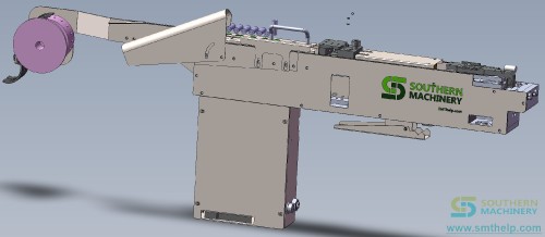
TO-90 90-Degree Bend Radial Lead Insertion: Low-Profile THT Automation
Tall radial parts — large electrolytic capacitors, film caps and high-body LEDs — don't fit slim LED drivers and adapters standing upright. Hand-bending each lead 90 degrees before insertion is slow, inconsistent, and a frequent source of bent leads and mis-insertion. The TO-90 builds that bend into the radial insertion cycle, laying the component flat against the PCB in one repeatable move.
The cost you haven't named: the standoff problem
Tall radial bodies quietly force bigger enclosures or manual workarounds that nobody prices into the line.
- Standoff breaks the enclosure limit. Tall radial bodies exceed the mechanical height budget of slim lamps, adapters and flat appliances, forcing either a bigger housing or a hand-bend workaround that slows the line.
- Hand-bent leads drift. Operators bend leads at slightly different angles, so components tilt and clinch inconsistently — defects that surface at wave soldering as lifted leads and poor joints.
- A manual station on the critical path. Pre-bending and inserting tall parts by hand keeps one operator tied to a step the auto-insertion line could otherwise absorb between SMT and wave.
- Tooling not on the radial platform. Without dedicated lead-forming tooling, the bend is a separate manual operation rather than part of the same insertion cycle, so the part changes hands twice.
The Four-Point Low-Profile Lead-Form Audit
Frame the capability as a qualification checklist for your tall-radial parts. Call it the Four-Point Low-Profile Lead-Form Audit.
1. Measure the standoff limit. Define the maximum assembled board height your enclosure allows, and identify which radial parts exceed it standing upright so the bend target is concrete, not assumed.
2. Classify the tall-radial set. List the tall electrolytic and film capacitors, coils and high-body LEDs by height (platform covers up to 20–22 mm) and lead diameter, so the bend tooling matches each part's body and span.
3. Define the bend-and-clinch rule. Confirm the 90-degree bend lands on the lead at the right position, and that clinch angle (0–45°) and length (1.28–1.80 mm) sit inside your IPC window before the board reaches wave soldering.
4. Set the inline target. State that the bent-lead operation runs inside the radial insertion flow — no separate manual pre-bend bench — feeding straight into wave soldering with the rest of the THT workload.
The vehicle: TO-90 90-Degree Bend Radial Insertion Station
The audit maps onto how the TO-90 is configured on the radial platform.
- Measure the standoff limit → machine-formed 90° bend. The lead-forming tooling bends tall radial leads 90 degrees as part of the insertion cycle, dropping assembled height from standing body height to roughly body thickness against the board.
- Classify the tall-radial set → platform envelope up to 20–22 mm. Built on the S3000/S3010A servo architecture, the station handles components up to 20 mm tall (S3000) or 22 mm (S3010A) with body diameters to 13 mm and lead spans of 2.5 / 3.5 / 5.0 / 7.5 / 10.0 mm.
- Define the bend-and-clinch rule → within IPC clinch window. Clinch angle and length are set to your IPC-based process window, so bent-lead parts lock in place and survive wave soldering without floating or shifting in the wave.
- Set the inline target → drops into the radial insertion flow. The TO-90 sequences with standard radial and odd-form insertion in the same THT cell, then hands off to wave soldering and inline lead cutting, cleaning and AOI in one scope.
Specification note: the 90-degree bend, platform height/diameter envelope, lead spans, PCB range (50 × 50 to 400 × 300 mm, 0.79–2.36 mm thick), clinch window and 10,000–20,000 CPH platform speed are configuration-dependent reference values, so final figures are confirmed at quotation against your BOM and panel drawings.
Specifications
| Parameter | Value |
| --- | --- |
| Bend angle | 90° lead bend (formed in insertion cycle) |
| Component height (platform) | up to 20 mm (S3000) / 22 mm (S3010A) |
| Body diameter (platform) | up to 13 mm |
| Supported lead spans | 2.5 / 3.5 / 5.0 / 7.5 / 10.0 mm |
| Insertion direction | 0° to 360° (0°–90° recommended for throughput) |
| PCB size range (reference) | 50 × 50 mm to 400 × 300 mm |
| PCB thickness | 0.79 – 2.36 mm |
| Clinch angle / length | 0°–45° / 1.28–1.80 mm |
| Throughput (platform) | 10,000–20,000 CPH spec; actual confirmed by demo |
The loop: re-check every enclosure revision
Enclosure limits tighten as products get slimmer. Build a loop: every enclosure or board revision, repeat the Four-Point Low-Profile Lead-Form Audit, re-measure the standoff budget, and re-confirm the bend position and clinch window on a demo part before ramping. Review the bent-lead geometry with your process leads so a new capacitor type doesn't reintroduce hand bending. The loop is what keeps the TO-90 on the auto-insertion line instead of letting a manual bench creep back in.
Your next step
Send us your tall radial component list and PCB panel drawings, and we will return a configuration and ROI review showing how the TO-90 90-degree bend radial insertion station fits your THT line, what envelope and clinch to specify, and what to confirm at quotation. Reach Jason at jasonwu@smthelp.com or on WhatsApp +86 13602562576.
FAQ
What components can a 90-degree bend insertion machine handle?
Tall radial-lead components — large electrolytic and film capacitors, high-body LEDs and similar parts whose standing height creates clearance problems. The platform's documented envelope covers components up to 20–22 mm tall with lead diameters around 0.7–0.8 mm; confirm your exact parts with the supplier.
Is the 90-degree bend done before or during insertion?
The bend is formed by the machine's lead-forming tooling as part of the insertion cycle — the component is fed, the leads are bent 90 degrees, positioned and inserted, then clinched. This removes the manual pre-bending step.
Does bending 90 degrees affect wave soldering quality?
When bend geometry is consistent, wave-solder results are more predictable because standoff and orientation are identical on every board. Confirm the clinch angle and length stay within your IPC-based process window.
Can this machine also insert standard upright radial components?
Yes. The 90-degree bend capability is tooling on the radial insertion platform, so the same machine can be configured for standard upright insertion of radial capacitors, transistors and LEDs alongside the bent-lead operation.
How does Southern Machinery support a THT line with this capability?
Southern Machinery supplies the full THT scope — radial/axial/odd-form insertion, wave soldering, board handling, lead cutting, cleaning and inspection — plus retrofit, spare parts and training, so the line is integrated and supported as one system.
Jason Wu
Founder & CEO, Southern Machinery (Shenzhen Southern Machinery Sales and Service Co., Ltd.)
Email: jasonwu@smthelp.com / info@smthelp.com
WhatsApp: +86 13602562576
Catalog & manuals: file.autoinsertion.com | Machine photos: ph.smthelp.com
LinkedIn: linkedin.com/in/smtsupplier | YouTube: youtube.com/c/Smthelping
Comments
Comments appear after approval.