
LED Display PCB Auto Insertion — Automate Hundreds of Radial LEDs per Panel
A P10 panel can carry hundreds of radial LEDs, each needing insertion, orientation and clinch. Run the Radial LED Insertion Audit, then see how the S3000 does it under machine vision.
Aug 22, 2026 · Updated Aug 31, 2026 · Jason Wu
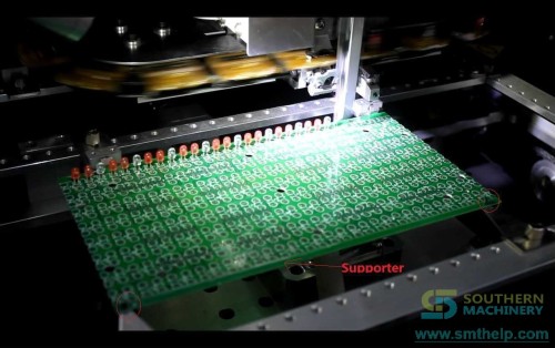
LED display module assembly is among the most insertion-heavy jobs in electronics manufacturing. A single P10 outdoor panel can hold hundreds of radial-lead LEDs, and every one must be inserted, oriented and clinched consistently. Southern Machinery — the Shenzhen SMT/THT automation company behind the S3000 and S3010A radial insertion machines — builds production lines that handle exactly this: LED display PCB auto insertion for P10 panels and general LED module assembly, with machine-vision coordinate correction.
The cost of manual LED insertion
Manual LED insertion is a classic source of THT defects:
- Reversed polarity when operators orient LEDs by eye across hundreds of placements.
- Bent leads and missed holes that show up as open circuits after wave soldering.
- Inconsistent clinch that weakens the joint and complicates downstream lead cutting.
- Throughput that does not scale — more LEDs per panel means more hands, not more boards per hour.
On high-count LED boards, these defects compound into rework that costs more than the insertion step itself.
The Radial LED Insertion Audit
Score your LED board before you automate. The audit uses your real module:
- Count LEDs per panel. How many radial LEDs does a P10/P3/P4 module carry, and how many panels per shift?
- List component specs. Body diameter, height, lead diameter (max 0.7 mm documented) and lead span (2.5–10.0 mm) determine feeder and head compatibility.
- Confirm lead form. Tape-packed radial components are required; loose or bulk parts need a different feeding solution.
- Define polarity and clinch. Insertion direction, polarity marking and clinch length/degree must match your downstream wave soldering and lead-cutting process.
The audit does not tell you to buy. It sizes the labor and rework your line loses on every LED module.
The Vehicle: how the S3000 inserts
An LED display PCB auto insertion machine is a radial-lead component inserter configured for through-hole LED components on display driver boards and module PCBs. It takes tape-packed radial components (LEDs, capacitors, transistors, key switches) from feeders, positions the PCB on a servo-driven table, inserts each lead into the correct hole, trims the leads and clinches them underneath — all under machine-vision coordinate correction, with no operator touching each component.
On Southern Machinery's S3000 platform, the process covers 0°–360° insertion direction in 1° increments, includes a servo-driven insertion head and clinch base, machine-vision calibration, and an English/Chinese control interface with offline programming software.
Where it fits in a complete line
A typical LED display module line built around Southern Machinery equipment flows like this:
- SMT section (for SMD driver ICs and passives on the same board): solder paste printing → pick and place → reflow oven → optional SPI/AOI.
- THT insertion section: the LED display PCB enters a loader/conveyor, then a radial insertion machine (S3000 / S3010A class) inserts all radial LEDs and through-hole components with vision correction and clinching.
- Soldering: the fully inserted panel passes through a wave soldering machine to solder all leads in one pass.
- Post-processing: lead cutting (S-320AT inline auto lead cutter), cleaning, inspection (AOI/AVI), and depaneling if the module is part of a larger panel.
Because insertion, trimming and clinching happen in one machine, downstream wave soldering receives consistently positioned leads — fewer bridges, fewer misses, less rework.
Verified S3000 platform specifications
| Parameter | S3000 (documented) |
|---|---|
| Machine type | Automatic radial component insertion machine |
| Speed | 18,000 CPH nominal, ~10,000 CPH actual (typical) |
| Insertion direction | 0°–360°, 1° increments |
| Lead spans | 2.5 / 3.5 / 5.0 / 7.5 / 10.0 mm (dual, triple, quad) |
| Component limits | Max height 20 mm; max body diameter 13 mm; max lead diameter 0.7 mm |
| PCB size | 50 × 50 mm to 400 × 380 mm |
| PCB thickness | 0.79–2.36 mm |
| Clinch length / degree | 1.5–2.2 mm / 10–35° |
| Motion & correction | Servo-driven head, machine-vision coordinate correction |
| Feeders | 10 stations recommended; tape-packed radial |
| Control | English/Chinese interface, offline programming |
| Power / air | 220 V AC single phase 50/60 Hz; air 0.6 MPa, 0.3 m³/min |
Specifications are published on the official smthelp.com S3000 product pages; confirm the configuration for your board and component mix before quoting.
Make it a recurring evaluation, not a one-off
LED module designs change with pitch and density. Re-run the Radial LED Insertion Audit when you add a panel size, change an LED type, or see polarity or clinch defects after a new product introduction. The same board program produces the same result every cycle — which is what downstream AOI and wave soldering depend on.
Your next step
Send your LED display module PCB file, component list (LED type, lead span, tape pitch) and target volume to info@smthelp.com or WhatsApp +86 136 0256 2576. The engineers confirm feeder configuration, insertion-head setup, clinch parameters and line layout, then quote the machine or full line. Southern Machinery (Shenzhen, China, since 2011, 237+ global customers) delivers complete SMT/THT solutions — insertion, wave soldering, board handling and inspection — from one source.
FAQ
What is an LED display PCB auto insertion machine? A radial-lead insertion machine (Southern Machinery S3000 / S3010A class) that automatically feeds tape-packed radial LEDs and THT components, inserts them under vision guidance, trims the leads and clinches them — replacing manual LED insertion on display module boards.
Which LED display types can it handle? Radial LED components on display driver boards and module PCBs — the same platform demonstrated on P10 panels and general LED display auto assembly. Pitch (P3, P4, P5, P10) is a board-design factor; confirm your module with the factory.
Does the machine handle polarity and orientation? Yes. The S3000 documents 0°–360° insertion direction in 1° increments, so LED polarity and orientation can be programmed per component type, with machine-vision coordinate correction.
What are the PCB size limits? The S3000 documents 50 × 50 mm minimum to 400 × 380 mm maximum PCB size, and 0.79–2.36 mm thickness. Larger or non-standard panels should be confirmed with Southern Machinery.
What components can be inserted? Radial-lead, tape-packed components: LEDs, capacitors, transistors, resistors, key switches and other compatible radial parts. Maximum documented lead diameter is 0.7 mm; lead spans from 2.5 to 10.0 mm.
How does this connect to a full PCB assembly line? The insertion machine sits in the THT section: boards arrive from SMT/reflow or a loader, LEDs and THT parts are inserted and clinched, then the board moves to wave soldering, lead cutting, cleaning and inspection. Southern Machinery can supply all these stages as one line.
Jason Wu
Founder & CEO, Southern Machinery (Shenzhen Southern Machinery Sales and Service Co., Ltd.)
Email: jasonwu@smthelp.com / info@smthelp.com
WhatsApp: +86 13602562576
Catalog & manuals: file.autoinsertion.com | Machine photos: ph.smthelp.com
LinkedIn: linkedin.com/in/smtsupplier | YouTube: youtube.com/c/Smthelping
Comments
Comments appear after approval.